Control diagram motor system block tachometer feedback fig shown thank solved Electrical control motor wiring types circuit schematics diagram panel engineering electronic symbols stop board switch eee resetsg mechanics info choose How to overcome the power-heat dissipation challenge in embedded motor
Mastering Motor Control Center (MCC): Wiring diagrams and equipment
Stepper motor control block diagram Motor control system structure diagram Block diagram of motor control.
Motor control system
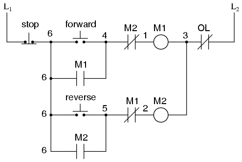
Motor control circuits switch logic ladder plc auxiliary contacts diagram electric forward contact program circuit seal reverse programming diagrams stopForward and reverse motor control diagram Control circuit diagramsPlc programming,plc ladder diagram, plc simulation,and plc training.
Motor control diagram system rs online flow singapore architecture motorer systems3 phase 2 speed motor wiring diagram pdf ⭐ motor control circuit wiring diagrams ⭐Motor control wiring diagram.

Dissipation overcome heat diagram
Motor circuits and control – applied industrial electricityMotor control diagram wiring switch float diagrams previous next Troubleshooting three basic hardwired control circuits used in startingMotor control: ac induction block diagram.
Block diagram of motor control systemForward and reverse motor starter with timer diagram Mastering motor control center (mcc): wiring diagrams and equipmentPhase motor wiring diagram.

Wiring diagram of motor control
Block diagram of the proposed motor control systemTypes of motor control schematics Stepper motor control system diagram block detailed components highlighted areas basic links shows information click massmindMotor control three circuits electric starting basic circuit troubleshooting starter phase electrical used autotransformer main after time hardwired typical voltage.
Solved the block diagram of a motor control system with[diagram] three phase motor control circuit diagram Control motor diagram reverse forward ladder circuits plc logic electric wiring programming circuit stop switch digital simulation lessons phase chapterMotor control system structure diagram.
Motor control part 1
Motor in circuit diagramMotor control circuits: electrical machines Mcc voltage mccs mastering diagrams zero hero vfds plcs they.
.


Motor Control Part 1 - Type of Power Electronic Switches - Magnequench

Motor Control: AC Induction block diagram - Electronic Products

Motor Control Wiring Diagram - Search Best 4K Wallpapers

Types of Motor Control Schematics | Electrical circuit diagram, Circuit

| RS

Forward and reverse motor control diagram - pasastep

Wiring Diagram Of Motor Control

Mastering Motor Control Center (MCC): Wiring diagrams and equipment