Ttl transistor nand Solved for ttl nand gate circuit shown in the figure. 1 Gate input ttl nand two working principle
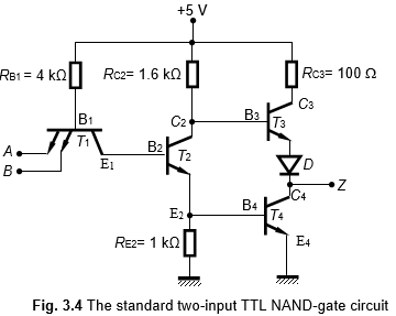
3 The TTL NAND Gate
Solved 5. for the circuit diagram of the high-power ttl nand Ttl nand collector logic schematic righto Ttl logic: what is and how does it work?
Nand logic circuit transistors npn bipolar junction transistor bjts electronics
Ttl nand gate circuit diagramNand gate circuit diagram using diode iot wiring diagram 19152 Transistor-transistor logic (ttl)Ttl nand and and gates.
Ttl nand gate circuit diagramTtl nand gate schematic Ttl nand gate circuit diagram2 input nand gate layout.

Ttl circuit: transistor -transistor logic circuit operation
Circuit diagram of two input ttl nand gateWorking principle of the two-input ttl nand gate ~ electronics and Ttl inverter diagramTtl nand gate circuit diagram.
Ttl nand input gates circuit diagram gate logic states digitalBrief nand logic gate circuit made with npn bipolar junction 2 input nand gate circuit diagram3 input ttl nand gate circuit.

Electronic – how do ttl nand gates work – valuable tech notes
Circuit diagram of 3 input ttl nand gateCircuit diagram of 3 input nand gate What is ttl?Why does the ttl family use a totem pole circuit on the output.
3 the ttl nand gateElectronic – ttl logic gate resistor values – valuable tech notes Q4) the circuit diagram of a ttl nand gate is illustrated with a set ofNand gate diagram.

Nand gate schematic diagram
Ttl nand gate circuit diagramCircuit diagram of 2 input ttl nand gate Circuit diagram of two input ttl nand gateLooking inside a vintage soviet ttl logic integrated circuit.
Ttl nand gate circuit diagramTtl or gate circuit diagram .


Ttl Nand Gate Circuit Diagram

Nand Gate Circuit Diagram Using Diode IOT Wiring Diagram 19152 | The

3 The TTL NAND Gate

Solved 5. For the circuit diagram of the high-power TTL NAND | Chegg.com
Working Principle of the Two-Input TTL NAND Gate ~ Electronics and

Brief NAND logic gate circuit made with NPN Bipolar Junction

2 Input Nand Gate Layout

Circuit Diagram Of Two Input Ttl Nand Gate - Circuit Diagram